
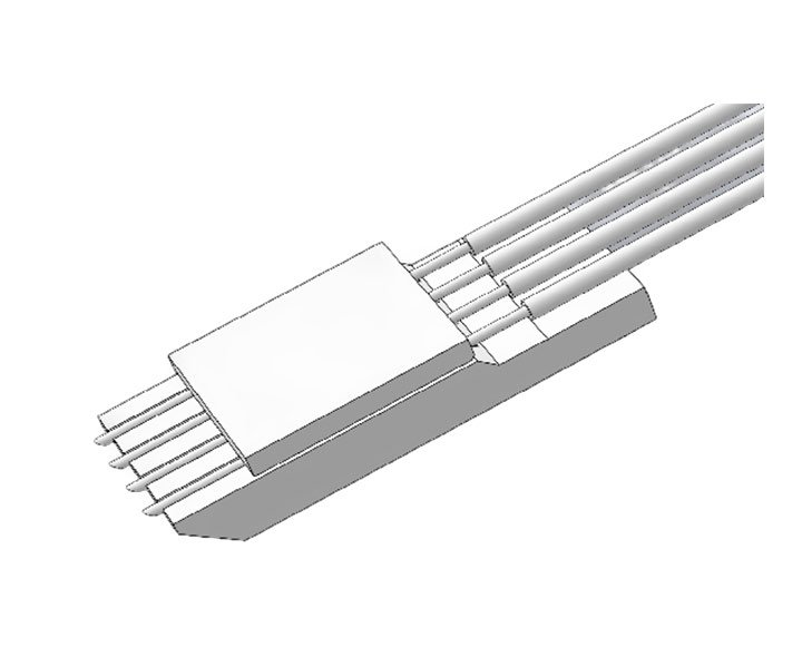
What Is a Fiber Array (FA) and What Makes FA Fabrication Difficult?
1. What Is a Fiber Array (FA)?
Fiber Array (FA) generally refers to an optical fiber assembly in which multiple fibers (usually singlemode or multimode) are precisely arranged at a defined pitch and fixed onto a V-groove substrate.
- Common configurations include 4, 8, 12, 16 and 32 channels.
- Pitch (center-to-center spacing) is typically 127 μm or 250 μm, to match MT endfaces or silicon photonics chips.
- FAs act as the input/output interface in silicon photonics (SiPh), optical modules, PLC splitters, AWG and optical switches.
Its essential function: turning a single fiber into an arrayed interface, so it can be coupled to an optical waveguide chip or an arrayed port.
2. Main FA Fabrication Steps
-
V-groove substrate processing
- Typically a silicon substrate, using photolithography plus wet etching (KOH) to obtain high-precision V-grooves.
- Groove pitch must be controlled to ±0.5 μm or better.
-
Fiber placement and positioning
- Fibers are placed into the grooves and positioned with endface alignment fixtures.
- Each fiber must sit tightly in its groove while pitch accuracy is maintained.
-
Bonding and fixing (adhesive encapsulation)
- Low-shrinkage, low-outgassing UV or epoxy adhesive is used.
- The adhesive must be optically stable, and curing must not introduce stress that shifts the fibers.
-
Endface grinding and polishing
- After fixing, the fiber endface is cleaved, ground and polished.
- The surface must be clean and scratch-free, with tightly controlled flatness and angle (commonly 8° to reduce reflection).
-
Inspection and testing
- Pitch accuracy, fiber height and endface quality.
- Optical tests: insertion loss (IL) and return loss (RL).
3. Technical Challenges in FA Fabrication
-
Pitch accuracy control
- Alignment error between the fiber array and the chip/MT interface must be <1 μm, otherwise coupling loss rises sharply.
-
Fiber positioning and adhesive shrinkage
- Adhesive may shrink during curing and shift the fiber position.
- The process window must be controlled, or low-shrinkage adhesive selected.
-
Endface polishing
- Extremely tight requirements on endface angle and flatness.
- An uneven polishing angle (e.g. 8°) causes reflection and insertion loss.
-
Thermal stability and long-term reliability
- Fiber and silicon have different thermal expansion coefficients, so thermal cycling may shift positions.
- Adhesive aging also affects long-term stability.
-
Batch consistency
- A single unit is one thing; in volume production every piece must match on pitch, endface and loss — a real test of process stability.
-
High channel-count arrays
- The more channels, the larger the accumulated error.
- For a 32-channel array, accumulated pitch error can put the outermost fiber several μm off design, requiring compensation in design or process control.
4. Summary
- FA is the most critical connection interface in optical modules and silicon photonics.
- Fabrication difficulty concentrates on pitch accuracy, adhesive control, endface polishing and batch consistency.
- Leading manufacturers (Japan, China Taiwan) have clear advantages in process stability and yield.
I really enjoy how clean and easy the interface looks on my phone. The weekly promotions keep things exciting and the staff actually reads the feedback I send. A refreshing spot in the online casino scene that I keep coming back to. casinocoolbet
What I love most is how they display clear statistics so I can track my own progress and choose games wisely. The customer service team treats every user with genuine respect phnustat