
Fiber Collimators
from a diverging cone to a parallel beam
A capillary holds the fiber, a lens turns the cone into a beam, and the housing keeps both aligned for life.
C-Lens or G-Lens, single or multi-fiber, standard or polarization-maintaining.
C-Lens / G-Lens
SM / MM / PM
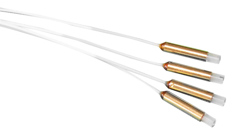
Four configurations
Single fiber is the default. Dual and quad are for pump combining and parallel paths; PM is for coherent and sensing work.
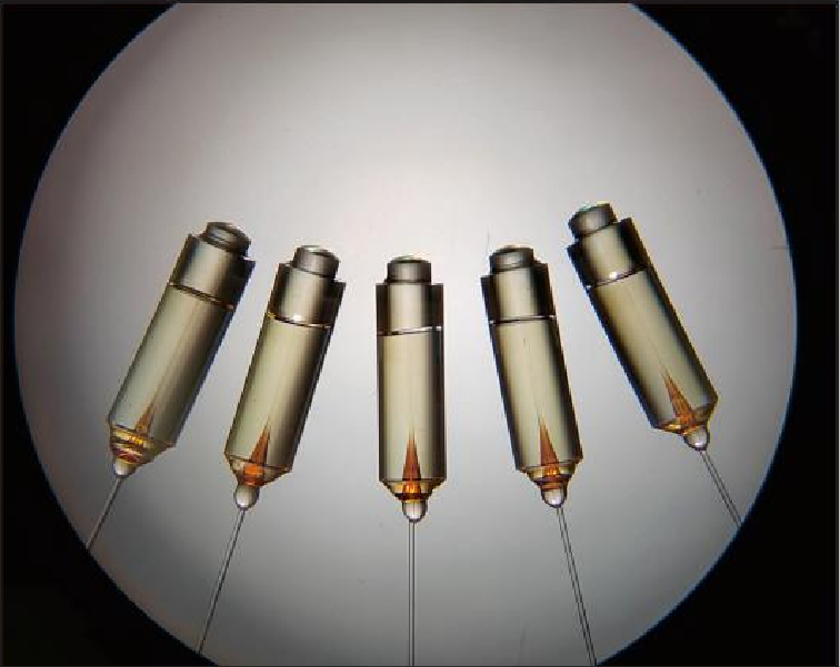
One fiber, one lens. The workhorse for isolators, circulators and free-space links.
Φ1.4 – Φ3.2 mm housing
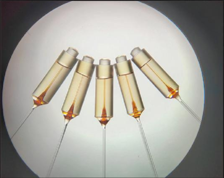
Two fibers into one lens — pump combining, duplex links, or a compact circulator substitute.
2CH · common lens
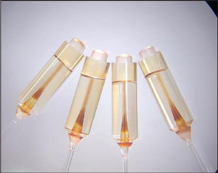
Four channels sharing one aperture, for pump/signal combining and array-type modules.
4CH · common lens
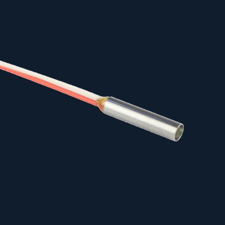
Polarization-maintaining fiber with keyed alignment, so the slow axis stays where the design needs it.
PM · keyed to axis
C-Lens or G-Lens
The short answer: inside 5 mm use G-Lens; beyond 20 mm or when return loss is tight, use C-Lens.
| Item | G-Lens (GRIN) | C-Lens (cylindrical) |
|---|---|---|
| Principle | Radial index gradient; light follows a sinusoidal path inside the glass | Spherical curvature; focusing by surface geometry |
| End face | Flat — easy to bond directly to fiber | Curved — needs a spacer or sleeve for positioning |
| Working distance | Short, typically under 5 mm | Long, workable beyond 20 mm |
| Loss over distance | Rises quickly with distance | Better IL and RL at long working distances |
| Typical use | Miniaturised, high-density packaging, short coupling | Optical switches, long coupling, MEMS arrays |
| Cost | Lower | Higher |
What is normally possible
Industry-typical values, provided so you can judge whether your requirement is conventional. Actual IL / RL are confirmed per part.
| Parameter | Typical range | Notes |
|---|---|---|
| Wavelength | 850 / 980 / 1310 / 1550 nm | Broadband and dual-wavelength available |
| Working distance | 5 / 10 / 15 / 20 / 30 / 50 mm | Longer distances require optical evaluation |
| Insertion loss | 0.25 dB typical, 0.35 dB max | Excluding connectors; connectorised adds about 0.3 dB |
| Return loss | ≥ 55 dB (APC facet ≥ 60 dB) | Depends on facet angle and polish quality |
| Beam diameter | 0.3 – 2.0 mm | Varies with lens and wavelength |
| Package size | Φ1.4×9 / Φ1.8×10 / Φ2.78×9 / Φ3.2×10 mm | Metal or glass housing |
| Fiber type | SMF-28 / 50-125 multimode / PM | Other core sizes on request |
| Operating temperature | -20 to +75 °C | Extended temperature evaluated separately |
| Power handling | 300 mW standard | Higher power needs an adhesive-free optical path |
Scope note The table is an industry reference, not our committed specification. For a given part, IL / RL / WD are confirmed in the datasheet after evaluation.
Where it goes
Four questions we get on collimators
Which four numbers do I need to specify a collimator?
housing. Add the required IL / RL if the application has a tight budget, and the connector type if it is
terminated.
Can one collimator cover two wavelengths?
one of the two. If the two wavelengths are far apart (850 and 1550 nm, for example), two separate parts are
normally cheaper than one compromised part.
How is PM axis alignment handled?
position is agreed on the drawing — usually referenced to the housing flat. Axis alignment error is quoted as
an angle, not as a vague “aligned” statement.
What limits power handling?
milliwatts. Above that, the design moves to an adhesive-free path (spliced or laser-fused), and the package
usually grows. Tell us the power level at the quoting stage — retrofitting is expensive.
Four numbers are enough to start
Wavelength, working distance, fiber type, package diameter. Send those and we will come back with a proposal.