
V-Groove Substrates
the datum for fiber arrays
The expensive microns of a fiber array live on this one piece of glass. Pitch, groove depth and wall angle
fix the centre of every fiber — and decide whether the end face can be polished to spec afterwards.
±0.5 μm centre-to-centre
parallelism better than ±0.1°

Three ways to buy the same groove
Same cut, three delivery forms — it depends on where you do the dicing and when you load the fiber.
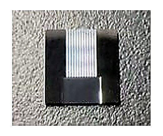
Cut to final size, ready for your fiber-loading line. Best for prototypes, small runs, or customers building their own FA capacity. Shown: 12CH silicon.
2 / 4 / 8 / 12CH · 127 / 250 μm
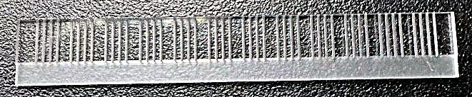
Twelve 4CH units on one substrate, delivered as a bar. You dice and load on your own takt; unit cost is lower than singulated parts.
12-up × 4CH · up-count configurable
Up-count, channels per unit and end facet angle are all specified by you. Shown: 20-up × 4CH with an 8° side facet.
20-up × 4CH · 8° side facet
Why a V-groove locates fiber below a micron
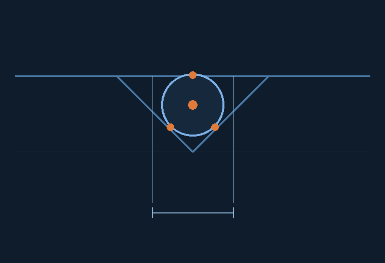
Fiber is a cylinder. Drop it into a V-groove and it touches two inclined walls plus the lid —
three contact points define one centre, uniquely. Groove width and depth are calculated
from the fiber radius, so the fiber has nowhere to move, sideways or vertically.
- Two points set X: the inclined walls clamp the fiber laterally; the core sits on the groove centreline.
- One point sets Y: the lid presses the fiber crown down to a fixed height above the groove face.
- Pitch is the fiber pitch: the diamond blade indexes at 127 / 250 μm, so core spacing equals groove spacing with no second alignment.
What we deliver today
These are our published capability values — the same numbers used in our quotation sheets.
| Parameter | Standard range | Notes |
|---|---|---|
| Channels per unit | 2 / 4 / 8 / 12CH | Higher counts and non-standard layouts on request |
| Bar up-count | 12-up / 20-up | Up-count and channels per unit combine freely |
| Pitch | 127 μm / 250 μm | For 125 μm bare fiber and 250 μm coated fiber |
| Adjacent groove centre accuracy | ±0.5 μm | Measured in-line, recorded per substrate |
| Parallelism along groove | better than ±0.1° | Drives fiber-height consistency after polishing |
| Substrate material | Quartz JGS2 / Borofloat 33 / silicon | Selected by CTE and polishing behaviour |
| L × W × T | Per drawing | Non-rectangular shapes, steps and stacked layers accepted |
| End face angle | 0° / 8° / 41° / 42.5° / 45° | Chosen by the reflection budget of the mating device |
| Angle tolerance | ±0.3° | Controlled at the polishing step |
| Reliability | TC / PCT | Thermal cycling and pressure-cooker testing |
Scope note Values above are our current deliverable range. Parameters not listed (groove wall roughness, end-face flatness figures) are confirmed per project — we do not publish numbers we have not measured.
Six questions engineers ask before ordering
What is the difference between a V-groove for optical modules and one for PLC splitters?
PLC arrays are butt-coupled at 0° with ribbon fiber, so the substrate stays a plain rectangular block.
Module arrays are often coupled at 41° / 42.5° or with protruding fiber, which changes the substrate
outline, the lid length and the polishing fixture. Tell us the device it goes into, not just the channel count.
Why 127 μm and 250 μm — can I have another pitch?
in the groove without stripping. Other pitches are cut with a custom blade, which means a tooling lead time
and a minimum quantity. Send the pitch and tolerance and we will confirm feasibility before quoting.
Quartz, borosilicate or silicon — how do I choose?
Borofloat 33 is cost-effective and fine for many module applications. Silicon is chosen when the substrate is
also a mechanical or thermal reference, and it can be etched rather than sawed.
Do you supply the lid as well?
design needs clearance over the fiber crown. We can also supply substrate and lid as a bonded pair,
or unbonded for customers who bond in-house.
How do you verify groove position?
groove run is checked optically. Records are kept per substrate and can be supplied with the shipment
when the project requires traceability.
Bar or singulated — which should I buy?
lowest unit cost. No dicing capability — buy singulated die and go straight to loading.
Still evaluating — start with singulated samples, then move to bars once coupling is validated.
A drawing, or just an idea?
Both can be evaluated. Give us channel count, pitch, substrate material and end-face angle first — the reply will be much faster.