
Fiber Arrays
2CH to 192CH, built on our own V-grooves
V-groove, bare fiber, lid, end-face polish — four steps before it counts as an FA. The same 4CH array can ship
flush, semi-protruding or protruding, and that single choice decides what it can be attached to.
flush / semi-protruding / protruding
0° / 8° / 41° / 42.5°
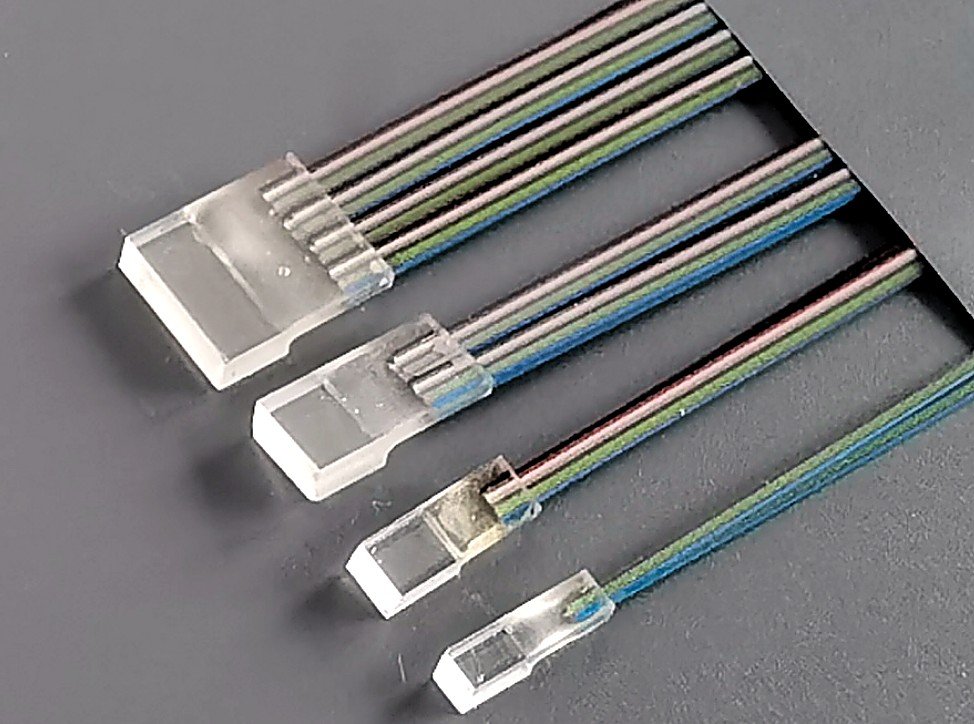
Flush, semi-protruding or protruding — decide this first
Same channel count, three end-face forms. It is not cosmetic: it decides the bonding surface and the pressure path.
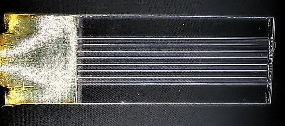
Fiber end face is coplanar with the substrate. The standard form for PLC, AWG and any butt-coupled device.
4CH · 250 μm · 0°
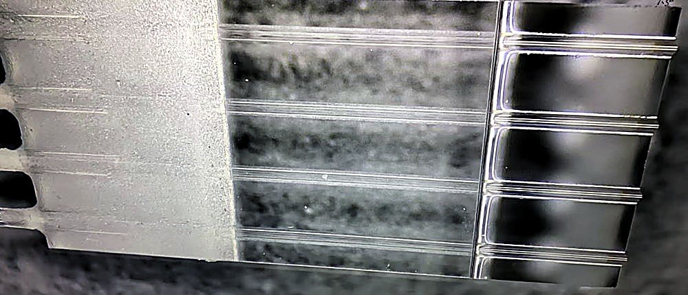
Fiber sits just above the substrate face, still protected by the lid — used where an adhesive layer sits between the array and the chip.
4CH · 750 μm · 42.5°
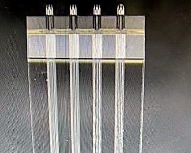
Fiber extends past the substrate so it can reach a waveguide or grating coupler directly. Protrusion must be uniform across channels.
4CH · 500 μm · 42.5°
How the other end terminates
The array end is the precision end. The far end is what the customer plugs into — and it changes the BOM.
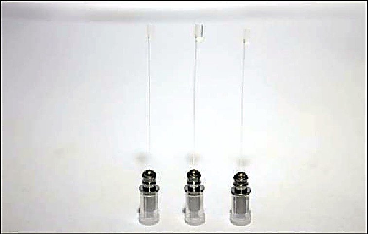
Single-channel array bonded into a metal receptacle — a drop-in collimator or detector port.
1CH · receptacle · 0°
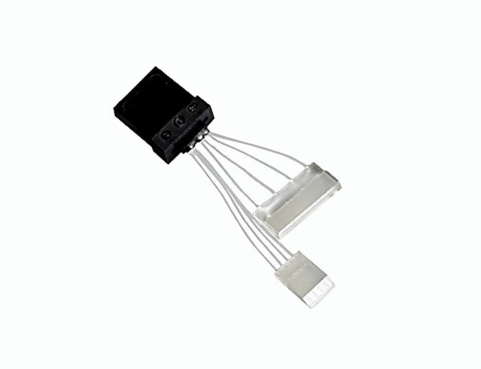
Array terminated into an MT ferrule for multi-fiber connectors and parallel optics.
4 – 24CH · MT ferrule
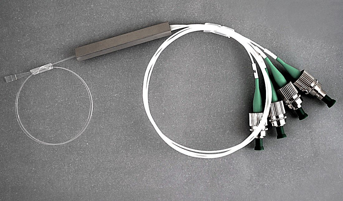
Polarization-maintaining array on a PLC, connectorised with keyed APC ferrules.
4CH · PM · FC/APC
Assembly note Connectorised and receptacle assemblies are built to order. Send the connector type, key orientation and fiber type, and we will confirm the assembly drawing before production.
Choosing the end-face angle
The angle is set by the reflection budget of the device — not by fashion. These are the five we cut most.
| Angle | Optical effect | Typical use |
|---|---|---|
| 0° | Normal exit, direct butt coupling | PLC splitters, AWG, standard coupling |
| 8° | Reflection diverted out of the optical path, return loss suppressed | RL-sensitive mating faces, connector side |
| 8° side | Face inclined 8° across the array axis | Bars and assemblies mated sideways — set by the mounting attitude |
| 41° | Total internal reflection, ~90° turn | VCSEL / PD to fiber vertical coupling |
| 42.5° | Refractive reflective coupling, saves module space | 400G / 800G modules, optical engines |
| 45° | Total internal reflection, 90° turn | Board-level optical interconnect, folded paths |
Caution 41° and 42.5° are frequently confused. They pair with different refractive-index and media combinations and are not interchangeable — when ordering, state the substrate material and the adhesive stack as well.
Array dimensions for PLC and module use
Standard ribbon arrays. Dimensions are the array datum; fiber type, ribbon colour and pigtail length are per project.
| Channels | Fiber configuration | A (mm) | B (mm) | C (mm) | Pigtail L (m) |
|---|---|---|---|---|---|
| 2CH (250 μm) | 2 × single bare fiber | 10±0.2 | 2.5±0.05 | 2.5±0.05 | 1.5 / 2.5 |
| 4CH (250 μm) | 1 × 4-fiber ribbon | 10±0.2 | 2.5±0.05 | 2.5±0.05 | 1.5 / 2.5 |
| 8CH (127 μm) | 2 × 4-fiber ribbon | 10±0.2 | 2.5±0.05 | 2.5±0.05 | 1.5 / 2.5 |
| 8CH (250 μm) | 1 × 8-fiber ribbon | 10±0.2 | 3.0±0.05 | 2.5±0.05 | 1.5 / 2.5 |
| 16CH (127 μm) | 2 × 8-fiber ribbon | 12±0.2 | 3.5±0.05 | 2.5±0.05 | 1.5 / 2.5 |
| 32CH (127 μm) | 4 × 8-fiber ribbon | 12±0.2 | 5.7±0.05 | 2.5±0.05 | 1.5 / 2.5 |
| 64CH (127 μm) | 8 × 8-fiber ribbon | 12±0.2 | 9.8±0.1 | 2.5±0.05 | 1.5 / 2.5 |
Note A / B / C are array datum dimensions; the final values follow your drawing. Ribbon colour, pigtail length and fiber type (SMF / MMF / PMF) are all project options.
Five questions before you specify an array
41° or 42.5° — how do I choose?
photodiode coupling, where the beam turns roughly 90°. 42.5° is a refractive geometry used when the module
needs a shorter optical path and the medium stack is designed for it. They are not interchangeable: the
coating, the adhesive index and the module drawing all differ.
Flush, semi-protruding or protruding?
Semi-protruding when an adhesive layer or a thin film sits in between: the fiber clears the
substrate face but is still protected by the lid. Protruding when the fiber must reach into a
grating coupler or a recess; here protrusion uniformity becomes the critical parameter.
Why polish an 8° facet at all?
Tilting the facet sends that reflection out of the guided mode. The trade-off is a slightly more complex
polishing fixture and a keyed mating part.
How is channel-to-channel consistency guaranteed on high-count arrays?
comb fixture so all fibers are seated in one action, and polishing is done on a fixture that keeps the array
flat. High-count arrays are also inspected for fiber height uniformity, not only for end-face angle.
Can you go beyond 192CH?
distribution all become limiting, and the design usually has to change (stacked layers or multiple arrays).
Send the layout and we will tell you honestly whether it is a single-array job or a multi-array assembly.
Five items and we can quote the same day
Channel count, pitch, end-face angle, termination and fiber type. With those five, the quotation is straightforward.